Brand:NTH
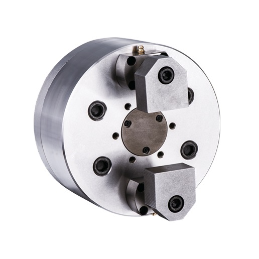
ꦏ To prevent deformation of workpiece for gripping the end surface, suitable for thin workpiece process.
෴ The compensating mechanism of gripping that can clamp irregular surface workpieces.
🐷 It can go with the check device to inspect the clamping status.


|
Spec Model |
Plunger stroke mm |
Jaw stroke Dia. mm |
Max chucking Dia. mm |
Min chucking Dia. mm |
Max.D.B.Pull KN(kgf) |
|---|---|---|---|---|---|
| 2F-05 | 12 | 8 | 53 | 25 | 5.0(510) |
| 2F-06 | 12 | 8 | 79 | 55 | 6.0(512) |
| 2F-08 | 12 | 8 | 106 | 75 | 12.0(1224) |
| 2F-10 | 12 | 8 | 150 | 119 | 12.0(1224) |
| 2F-12 | 12 | 8 | 200 | 169 | 12.0(1224) |
|
Spec Model |
Max clamping force kgf |
Max RPM |
I kg*m2 |
Weight kg |
Matched cylinders |
Max Pressure Mpa(kgf) |
|---|---|---|---|---|---|---|
| 2F-05 | 4.0(408) | 4000 | 0.015 | 9 | S-100R/SNK-100 | 0.7(7) |
| 2F-06 | 5.0(510) | 4000 | 0.035 | 9.8 | S-100R/SNK-100 | 0.8(8) |
| 2F-08 | 11.0(1122) | 3500 | 0.12 | 20.3 | S-100R/SNK-100 | 1.7(17) |
| 2F-10 | 11.0(1122) | 3500 | 0.28 | 30.7 | S-100R/SNK-100 | 1.7(17) |
| 2F-12 | 11.0(1122) | 3000 | 0.52 | 41.2 | S-100R/SNK-100 | 1.7(17) |
Spec
Model
A
B
C
D
F
G Max
G Min
J
J1
K
2F-05
135
86
110
82.6
40
75
55
25
10
M12×1.75
2F-06
165
86
140
104.8
45
75
55
28
14
M16×2
2F-08
210
90
170
133.4
56
80
60
38
16
M20×2.5
2F-10
254
95
220
171.4
56
75
55
38
16
M20×2.5
2F-12
304
95
220
171.4
56
75
55
38
16
M20×2.5
Spec
Model
L
L1
M Max
M Min
N
P
Q
R
S
T
U
2F-05
M10
15
56
36
20
M10
42.5
27
4-M6
50
30°
2F-06
M10
15
56
36
20
M10
57.5
40
4-M8
64
50°
2F-08
M12
18
71
51
25
M12
77.5
53.5
6-M8
104
50°
2F-10
M16
24
71
51
25
M12
99.5
75.5
6-M8
140
50°
2F-12
M16
24
71
51
25
M12
124.5
100.5
6-M8
190
50°
Subject to technology changes without prior information
Non-standard requirements can be made
Next:DPR 3 JAW PULL BACK POWER CHUCKS
Previous:3F 3 JAW FINGER POWER CHUCK